Reverse Engineering
Feature based solid modeling, parametric modeling & rapid surfacingVideo Demo- Reverse Engineering Solution using Geomagic Design X
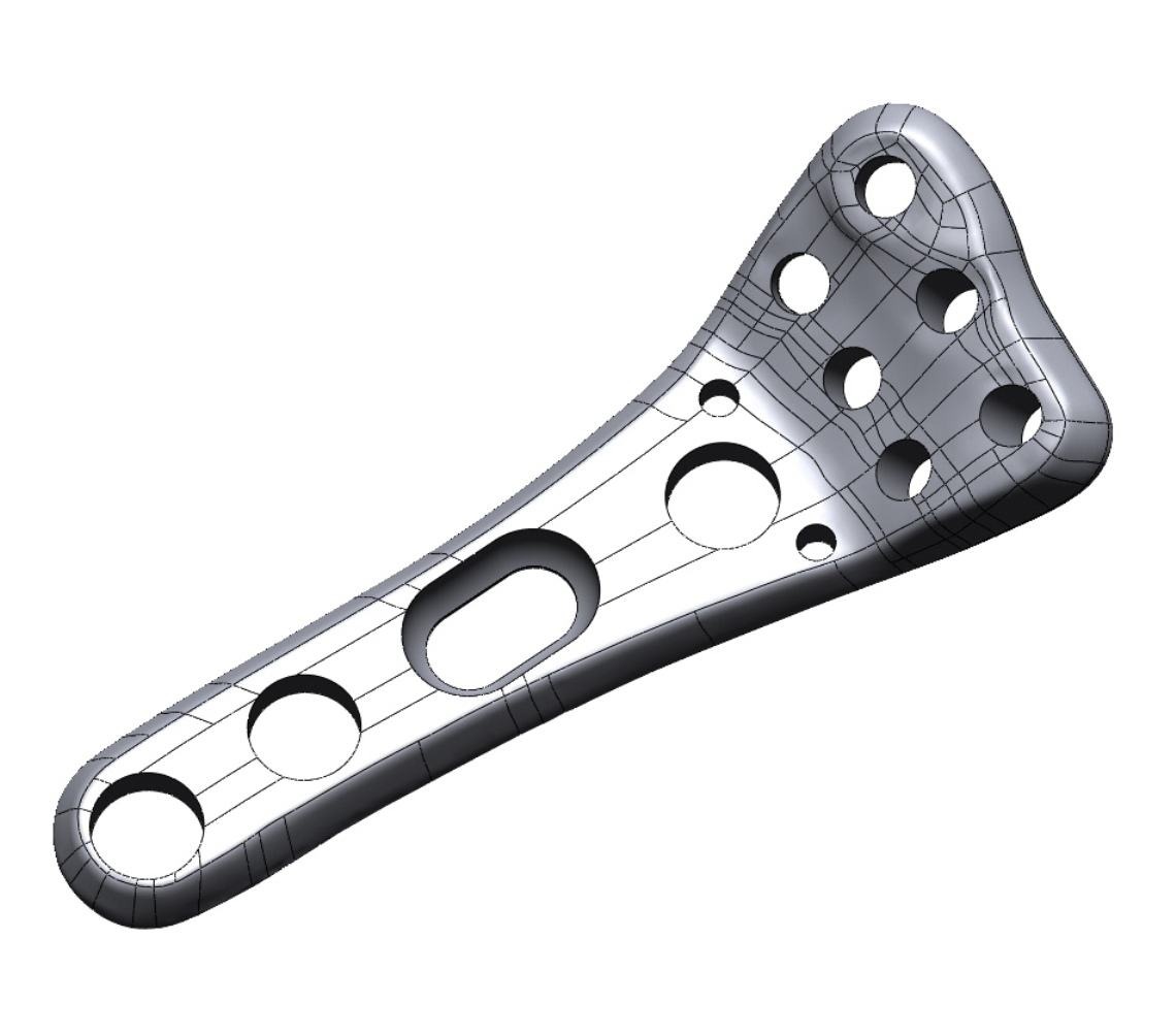
A parametric model is composed of primitive geometric features, trimmed surfaces, fillets & radii. Geometry is developed using traditional solid modeling techniques such as sketching and extruding, using the underlying scanned data as a reference. Entire model history is transferred into Solidworks upon completion in order to facilitate future design changes.
File Format: Solidworks (sldprt)
A feature based model is composed of primitive geometric features, trimmed surfaces, fillets & radii. Geometry is developed using traditional solid modeling techniques such as sketching and extruding, using the underlying scanned data as a reference. Original feature geometry may be extracted after import into customer CAD system. The only difference between a feature based model and a parametric model is that the Parametric model contains model history, and the feature based model does not.
File Format: iges, step, parasolid, Solidworks (sldprt)
A rapid surface model is developed using a quilt of smooth NURBS surface patches that are “shrink-wrapped” onto the polygonal mesh to create a model suitable for import into CAD. Upon CAD import, surfaces are knit together to form a static, or non-parametric solid. Rapid surface models are useful for highly complex shapes such as organic forms, art & sculpture or intricate castings. This technique is not generally recommended for mechanical components with a lot of geometric features.
File Format: iges, step, parasolid, Solidworks
A hybrid model will contain characteristics of both a Feature Based Model as well as a Rapid Surface Model. It is developed using a variety of techniques in order to develop a model that has both mechanical as well as free-form or organic geometric features.
File Format: iges, step, parasolid, Solidworks (sldprt)
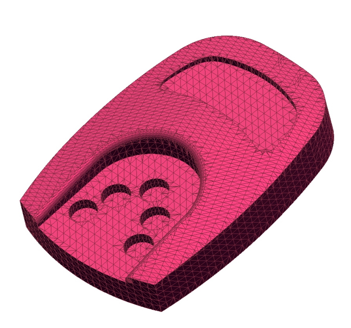
A polygon mesh can either be the starting point or end result of a 3d scanning or reverse engineering project. Raw data from most scanners today is export as a polygon mesh in STL or OBJ format. These data sets are often used as the starting point for CAD modeling. However, it is interesting to note that mostly all 3D printers operate using polygonal meshes in STL format. This mesh must be “water tight”, with no holes or defects. As such, raw scanned data must be post processed to some degree in order to generate a printable file.
File Format: STL, OBJ, VRML, PLY


Features Case Studies:
3D Scanning & Reverse Engineering an Aircraft
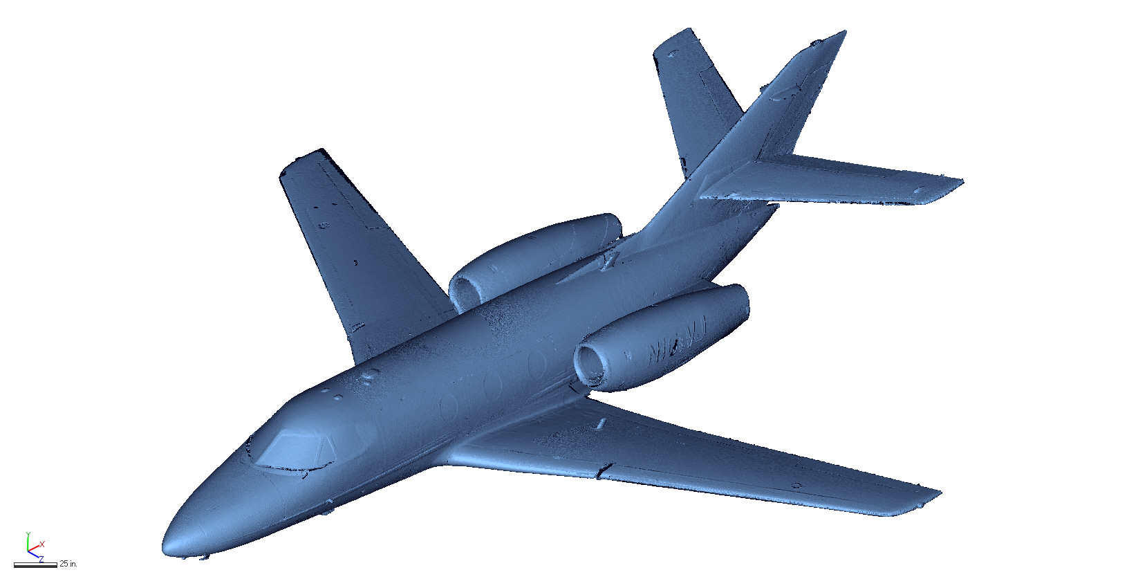 To capture the exterior of the plane, the Faro Focus long-range scanner was chosen for its ability to cover a lot of area in a relatively short period of time. Scans were taken in many different positions around the plane, including shots from above with the use of a lift. The full interior was also scanned with the Focus for general feature layout.
For the various internal components, the Creaform MetraSCAN handheld system was chosen due to its unique ability to take accurate measurements in harsh metrology environments. It’s wide temperature working range, and capability to track the part even when under vibration or movement made it perfect to scan directly in the hangar.
Continue Reading
3D Scanning & Reverse Engineering Auguste Rodin’s “The Thinker”
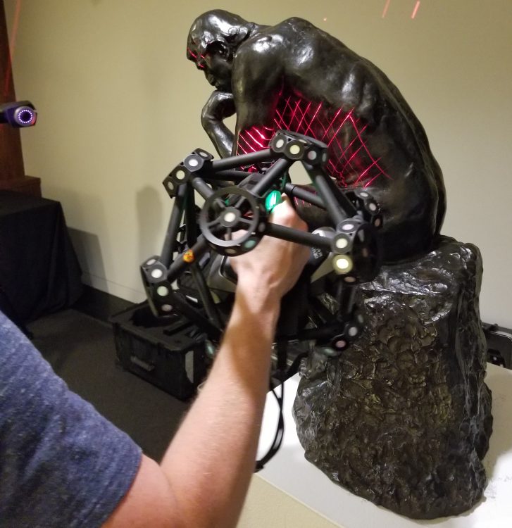 Using our MetraSCAN 750 3D scanner from Creaform, we are able to create a 3D duplicate of any physical object. With the MetraSCAN, we are able acquire 3D scan data with a level of accuracy of up to .0001 mm in just a matter of minutes.The MetraSCAN uses a bar with cameras and LED’s called the C-Track that is able to track the location of the handheld scanner. This setup method allows users to conduct scans on objects without having to place reference targets on the object’s surface.
Continue Reading
3D Scanning & Reverse Engineering a Transmission Case
![]() We offer quick reverse engineering solutions. We can digitally replicate any part whether it is no longer in production, or its designs are outdated. We do so using the Creaform HandySCAN. This 3D scanneris portable, easy to set up and accurate collecting data points within 0.001 – 0.002 inches.
We offer quick reverse engineering solutions. We can digitally replicate any part whether it is no longer in production, or its designs are outdated. We do so using the Creaform HandySCAN. This 3D scanneris portable, easy to set up and accurate collecting data points within 0.001 – 0.002 inches.
The setup includes calibrating the scanner, which takes one minute, and then the part is targeted up to provide points of reference for the HandySCAN. The targets allow the part to be moved and repositioned to ensure the entire surface is scanned. Unlike other scanners, the HandySCAN handle vibrations and movements while not sacrificing quality in the scan. The result is a 3D mesh model that provides accurate 3D data which the client can use to create an accurate parametric model and attain measurements instantaneously without doing any by hand. A CAD model can be modeled directly from the .STL which results in quicker modeling with higher quality.
Continue Reading
3D Scanning & Reverse Engineering a Pistol Grip
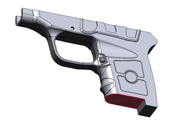 Using the Steinbichler L3D Laser Scanner, a scan of a small volume object is captured within an hour and exported as an STL file. The scanner produces data that is accurate within 0.001 inches. In this case, the grip handle of the Taurus Spectrum is scanned, and the mesh can be seen in figure 4. The scanner is able to digitally replicate every detail on the gun grip with incredible accuracy.
As previously mentioned, the customer needs a solid model with a high level of accuracy primarily around the trigger where the laser would mount. In order to use the mesh data from the scan, some maintenance needs to be performed on the mesh using Geomagic Wrap. Wrap provides tools to clean any features in the mesh such as holes or bumps along the surface.
Continue Reading
3D Scanning & Modeling of a Boat Hull and Deck
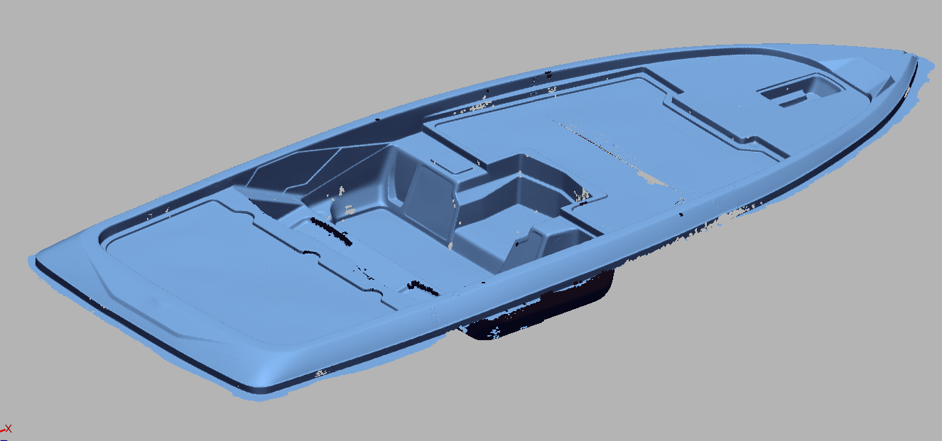 3D scanning is the perfect solution to this problem. Boats have many complex surfaces that cannot be easily measured. 3D scanning collects millions of points of extremely accurate data.
First the boat components are scanned with long range and short range scanners. Using the combination of short and long range capturing, a high amount of data can be captured with minimal error buildup.
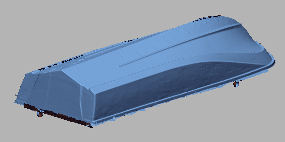 This data is then imported into Geomagic DesignX, a powerful reverse engineering software. The imported data is easily aligned and merged using straightforward built-in wizards and tools. From the scan data, a fully defined 3D model is created, using standard and complex modeling tools.
This model is then sent to Gregg in a standard CAD file format. He can then take this file and modify it per his customer’s design goals.
Continue Reading
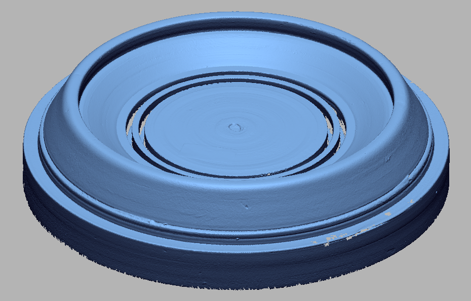
3D Scanning & Modeling Tooling
 NeoMetrix uses the latest in 3D scanning technology to be able to capture complex geometry quickly, efficiently and accurately.
The scanner chosen for this project is the Creaform MetraSCAN. The MetraSCAN is a powerful laser scanning system that uses a tracking bar (C-Track) to track the location of the scanner. This means that the object being scanned needs minimal or no reference targets. The laser scanner itself records hundreds of thousands of data points per second, allowing for very quick data acquisition.
Each tool is positioned in front of the C-Track, and is then scanned. With the fast data
capture rate, each tool can be scanning in a matter of minutes. Once the tools are all scanned, the scan data is directly imported into Geomagic DesignX, a powerful reverse engineering software package. Once the data is imported, a model can be created. Using simple sketch tools, a profile of the tool can be extracted from the scan. This sketch can then be revolved to create the entire tool.
This solid file is then exported as a parasolid (or any other standard CAD file type) and then delivered to Metal Industries. They can then use this file to manufacture new tooling.
Continue Reading
Development of Quick Connect Prosthetic Joint

The NeoMetrix method of reverse engineering employs the use of 3D scanning technology for rapid and accurate data collection of complex geometry. The scanner of choice for this project was the Zeiss Comet L3D. Rajesh’s joints scanned into CometPLUS software. The captured data was directly output as a triangulated mesh or STL file.
This mesh was then imported into Geomagic’s Design X reverse engineering software, where it was used as the guideline for generating the new CAD model of the part. Cross-sectional sketches were developed based upon the scanned data and subsequently used to generate solid bodies through traditional modeling methods, such as extrudes, lofts & sweeps.
Design X also allows for comparison of the final model back to the original scanned data to ensure accuracy to the original part to ensure that the new joint attachments would fit snugly and securely.