Problem:
EPRI, a nuclear power research division needed to accurately model a 40 inch diameter pipe that was welded inside a nuclear reactor. Data was required in order to custom fit ultrasonic inspection Sensors. (Figure 1)
Traditional Method:
Original design data for weld radius was used for probe development; however, as-built conditions did not match prints. This results in poor inspection results from ultra-sonic inspection.
NeoMetrix Solution:
3D Laser Scanning:
One engineer was sent down a week prior to scanning to have on-site nuclear plant training. Using photogrammetry each nozzle was laid with dots to ensure accurate data around the entire pipe. Finally, a light weight hand held scanner was used to scan the surface of each nozzle around the entire circumference.
- Parts scanned with Z-700 Hand held scanner for tight quarters
- Rapidform XOR used to interpolate missing data due to immovable objects (Figure 2)
- Surface modeled to the scan data
- Design data modeled for inside diameter
Merged and Scaled:
The drawback in the plant was that some material could not be removed to scan the pipe underneath it. This caused an issue in modeling spray nozzles and other extras on the pipe. Neometrix was able to combine design data from EPRI with data extrapolated from the scans to create the most accurate 3D models of each nozzle ever created.
NeoMetrix Advantage:
- Accurate and Repeatable results.
- 3D Animations for presentations (Figure 3)
- Ability to inspect back to original design.
- 2D sections from scanned data can be used to design new probes which exactly match as-built conditions.
Get Started Today
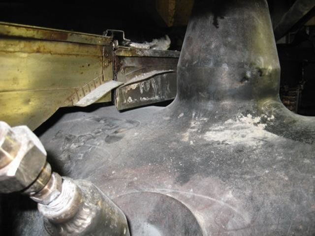
Figure 1 – Nozzle in Nuclear Plant
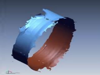
Figure 2 – Laser Scanned Data
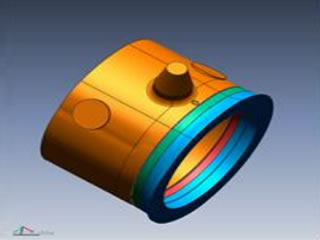
Figure 3 – 3D Solid Model